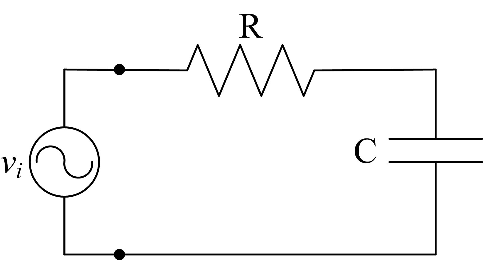
Well, I have a series electrical CR-circuit. In order to deliver the most output-power I need to solve:
$$\text{X}_\text{C}=\text{R}=\left|\frac{1}{\text{j}\omega\text{C}}\right|=\text{R}=\frac{1}{\omega\text{C}}\space\Longleftrightarrow\space\omega=2\pi\text{f}=\frac{1}{\text{RC}}\space\Longleftrightarrow\space\text{f}=\frac{1}{2\pi\text{RC}}\tag1$$
Where $\text{j}^2=-1$ and $\text{f}$ is the frequency.
But how can I show that this will be the frequency where the ouput stage (the resistor $\text{R}$) will receive the most possible power?
My work:
I can set up the following system of equations for a series electrical CR-circuit:
$$\begin{cases} \text{U}_\text{in}\left(t\right)=\text{U}_\text{C}\left(t\right)+\text{U}_\text{R}\left(t\right)\\ \\ \text{I}_\text{C}\left(t\right)=\text{U}_\text{C}'\left(t\right)\cdot\text{C}\\ \\ \text{U}_\text{R}\left(t\right)=\text{I}_\text{R}\left(t\right)\cdot\text{R}\\ \\ \text{I}_\text{in}\left(t\right)=\text{I}_\text{C}\left(t\right)=\text{I}_\text{R}\left(t\right) \end{cases}\space\space\space\space\space\space\space\space\space\space\space\space\space\therefore\space\space\space\space\text{U}_\text{in}'\left(t\right)=\frac{1}{\text{C}}\cdot\text{I}_\text{in}\left(t\right)+\text{R}\cdot\text{I}_\text{in}'\left(t\right)\tag2$$
Now, for the output power I can write:
$$\text{P}_\text{out}\left(t\right)=\text{U}_\text{out}\left(t\right)\cdot\text{I}_\text{out}\left(t\right)=\text{P}_\text{R}\left(t\right)=\text{U}_\text{R}\left(t\right)\cdot\text{I}_\text{in}\left(t\right)=\text{R}\cdot\text{I}_\text{in}^2\left(t\right)\tag3$$
Now, in order to find the maximum:
$$\text{P}_\text{out}'\left(t\right)=\text{P}_\text{R}'\left(t\right)=\frac{\partial}{\partial t}\left(\text{R}\cdot\text{I}_\text{in}^2\left(t\right)\right)=2\cdot\text{R}\cdot\text{I}_\text{in}\left(t\right)\cdot\text{I}_\text{in}'\left(t\right)=0\tag4$$
I can solve equation $\left(2\right)$:
$$\text{I}_\text{in}\left(t\right)=e^{-\frac{t}{\text{RC}}}\cdot\left\{\frac{1}{\text{R}}\int\text{U}_\text{in}\left(t\right)\cdot e^\frac{t}{\text{RC}}\space\text{d}t+\text{K}\right\}\tag5$$

$$U_{in}'=\dfrac{1}{C}I_{in}+RI_{in}'$$
For circuits, the idea is study the frequency response under "alternating current" voltage, using $U_{in}=V_0e^{j\omega t}$ ($\omega=2\pi f$) as the forced/applied voltage. The actual currents and voltages can be recovered taking the real part of the solution. The solution of this equation is,
$$I_{in}=C_1e^{-t/RC}+\dfrac{V_0Cj\omega}{CRj\omega+1}e^{j\omega t}$$
The first term of the rhs is the transitory part. Note that the term vanishes very quickly and in for a (not so in practice) large number of cycles is under the discernible and is taken as zero. The second one is the stationary regime. So, we have to study this equation:
$$I_{in}=\dfrac{V_0Cj\omega}{CRj\omega+1}e^{j\omega t}$$
We have now $C,R, V_0$ fixed and consider $\omega$. You can see now the futility of trying to find the extrema of this function as it has a pole, where the current "explodes". The pole is at
$jCR\omega=-1$
$\vert j\omega\vert=\left|-\dfrac{1}{RC}\right|\implies \omega=\dfrac{1}{RC};$
Added
As can be considered, it is not a complete response for the whole thing about circuits and maybe this answer requires some unexpected "tunning". e.g. I've seen it's not explained the complex impedance $X_C$, better belonging to the specifities of the topic. Anyway, we can simply understand that $X_C=\left|\dfrac{1}{j\omega C}\right|$